somewhere to talk about random ideas and projects like everyone else

stuff

ShinyTouch zero-cost optical touchscreen retrofit

You can make any flat, semi-reflective surface into a multitouch tablet with nothing more than an ordinary webcam pointed at an angle. Critically, it's possible to extract 3D information from a scene captured by a 2D camera by measuring the distance between an object and its reflection about a known surface.

ShinyTouch won 1st place at the Fairfax County Regional Science and Engineering Fair, and competed at the Virginia State Science Fair. It was recognized by the Optical Society of America (where I recieved a book punnily titled Optics Made Clear), the US Patent Office and the IEEE.


posts

ShinyTouch/OpenCV 15 July 2010

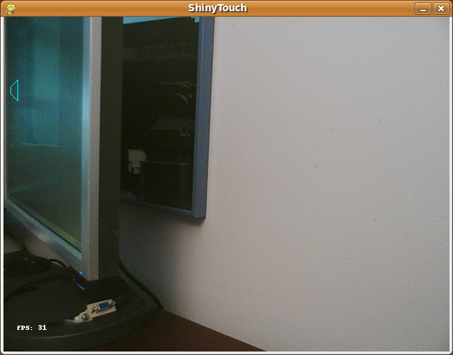
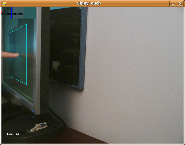
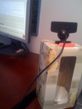
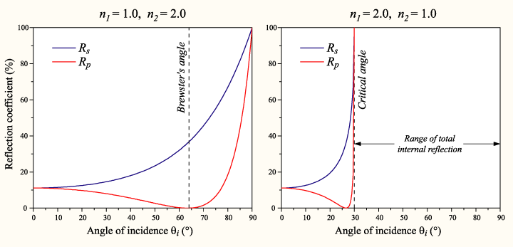
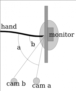
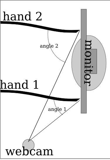
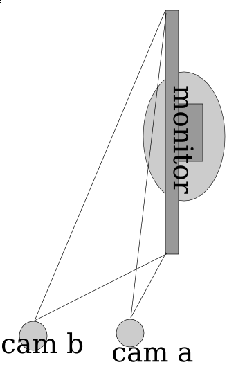
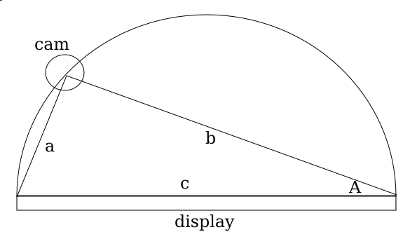
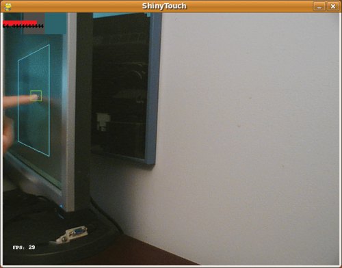
I have yet to give up entirely on ShinyTouch, my experiment into creating a touch screen input system which requires virtually no setup. For people who haven’t read my posts from last year, it works because magically things look shinier when you look at it from an angle. And so if you mount a camera at an angle (It doesn’t need to be as extreme as the screenshot above), you end up seeing a reflection on the surface of the screen (this could be aided by a transparent layer of acrylic or by having a glossy display, but as you can see, mine are matte, but they still work). The other pretty obvious idea of ShinyTouch, is that on a reflective surface, especially observed from a non-direct angle, you can see that the distance from the reflection (I guess my eighth grade science teacher would say the “virtual image”) to the apparent finger, or “real image” is twice the distance from either to the surface of the display. In other words, the reflection gets closer to you when you get closer to the mirror. A webcam usually gives a two-dimensional bitmap of data (and one non-spatial dimension of time). This gives (after a perspective transform) the X and Y positions of the finger. But an important aspect of a touchscreen and what this technology is also capable of, a “zero-touch screen”, is a Z axis: the distance of the finger and the screen. A touchscreen has a binary Z-axis: touch or no touch. Since you can measure the distance between the apparent real finger and it’s reflection, you can get the Z-axis. That’s how ShinyTouch works.

Last year someone was interested and actually contributed some code. Eventually we both agreed that my code was crap so he decided to rewrite it, this time using less PIL and pixel manipulation, and instead, opting for more OpenCV so it’s faster. The project died a bit early this year, and with nothing more to do, I decided to revive it. His code had some neat features:

  • Better perspective performs
  • Faster
  • Less Buggy
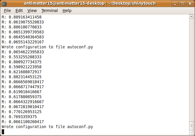
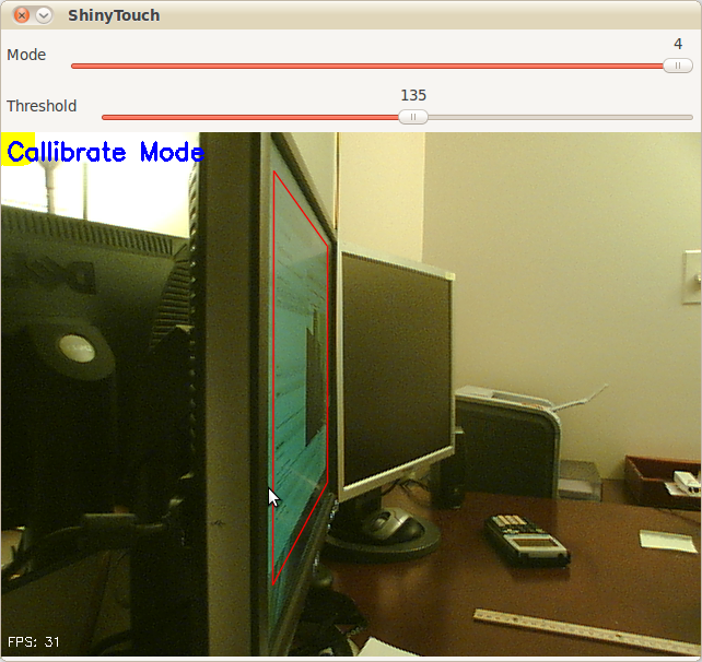
  • Simpler configuration (track bars instead of key combinations and editing JSON files)
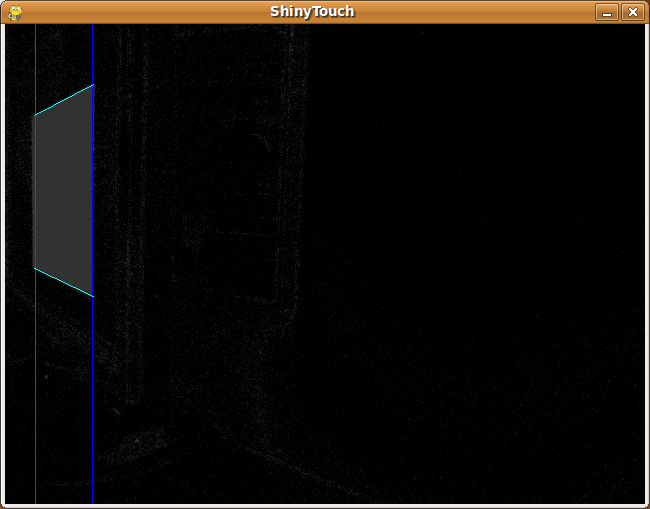
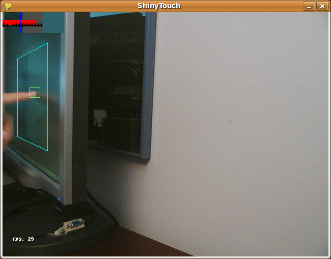
  • Yellow square to indicate which corner to click when callibrating (actually, I wrote that feature) It was left however, at a pretty unfinished state. It couldn’t do anything more than generate config files through a nice UI and doing a perspective transform on the raw video feed. So in the last few days, I added a few more features.

  • Convert perspective-transformed code into grayscale

  • Apply a 6x6 gaussian blur filter
  • Apply a binary threshold filter
  • Copy it over to PIL and shrink the canvas by 75% for performance reasons
  • Hack a Python flood-fill function to do blob detection (because I couldn’t compile any python bindings for the opencv blob library)
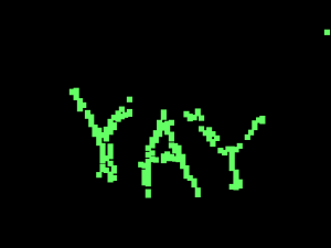
  • Filter those blobs (sort of) Basically, it means ShinyTouch can now do multi-touch. Though the Z-axis processing, which is really what the project is all about still sucks. Like it sucks a lot. But when it does work (on a rare occasion), you get multitouch (yay). If TUIO gets ported (again), it’ll probably be able to interface with all the neat TUIO based apps.

Code here: http://github.com/antimatter15/shinytouch/ Please help, you probably don’t want to try it (yet).


ShinyTouch/JS 28 August 2009

Yay for yet another demo that strives to mix an mash almost everything HTML5 related! ShinyTouch in JS dumps the stuff from a <video> tag with ogg encoded video (well, almost all video from linux is ogg encoded so it’s just whatever format i got first from cheese). It gets dumped into <canvas> and getImageData does it’s magic.

Interestingly, if you don’t use the video and just do data from a raw image, you get upwards of 125fps on V8. Adding the video, it ceases to work on Chromium (maybe a linux thing? this tells me it’s just linux, but you can never be so sure).

//At this point, run away as the algorithm gets messy and hackish

So the thing just searches from right to left up to down within the quad. When it finds a column of something that fits the rgb range of the finger that is larger than a certain threshold, it checks for a reflection from the point. If it detects a reflection then yay! it throws the data at the perspective warper (based on a python one which is based on a C# one and though it would probably be easier to port from C# to JS making long chains of derivative work is fun). If there wasnt a reflection then it logs that and if that number is larger than some othe rthreshold then it kills the scanning and goes on with it’s life. The reflection algorithm just takes the point 5 pixels to the right and assumes that would be a reflection if there was one and a point 15px above and 5px to the left (nasty stuff) and takes the hue value from their RGB values. It takes the absolute value of the difference of the hue values multiplied by 100 (or 200 in the python version) and compares it with a preset configuration variable.

So now that that horrible algorithm which was just whatever came to my little totally untrained mind first. But it works semi-decently, at least for me. But you can hopefully see how nasty it’s inner workings are and it inspires people to clean it up. It’s quite a bit more readable than the Python version and only 200 lines of JS so it won’t be too hard to understand.

But since HTML5 has no Video capture thing for webcams, and my webcam doesn’t work with flash so I can’t use that canvas<-flash webcam bridge i built, uh, almost 2 years ago. So now you just get to gaze at my finger moving for like 20 seconds!

http://antimatter15.com/misc/shiny/shinytouch.html


ShinyTouch Videos 26 August 2009

The first one is shot from recordMyDesktop-gtk and the second one is from Cycorder on my iPhone.


Shinytouch Perspective Transform 23 August 2009

Shinytouch perspective transforms now work!

One big issue with ShinyTouch is that it didn’t transform points correctly, but now it has been totally resolved by stealing this (MIT licensed) from the linux (python!) port of Wiimote Whiteboard (Johnny lee’s famous work). Now it works totally insanely awesomely, no elitists necessary.


TUIO Support 01 August 2009

So even though the algorithms that transform the calibration box aren’t working accurately yet, TUIO support has been made, so you can use apps like TUIO Mouse to control your computer and other touch demo things.


ShinyTouch Images 01 August 2009

This is the app running, notice that it’s not yet been calibrated yet.

Here is the auto-calibration process, it alternates between black and white

This is part of Auto-Calibration.

This is some stuff from the command line:

This is just hovering over the screen, notice it’s not touching, and the algorithm can distinctly recognize the lack of a touch because the reflection is seperated from the finger by a significant gap. (Compare the top red bar).

This is a actual touch, you can see that the red bar is far larger, and it’s very distinctly a touch event.

There’s a draw tool and, here is a primitive drawing of a smiley. The dots come from an issue with PIL/OpenCV or something that makes the image all chopped up and sends the point to an arbitary point on the screen.

This is the magical sensor the whole thing is powered by: An unmodified Playstation 3 Eye on a tissue box with a pink Office Depot eraser on the back (because the camera is made tilted and the script can’t handle those tilts very well)

It’s not too insanely slow either. This is 31 frames per second coming from a pure python app, all from a scripting language. It is nowhere as fast as the normal fast native apps.


ShinyTouch is 1 month old 28 July 2009

For as long as my notes show, ShinyTouch is now 1 month old.

So today, I added VideoCapture support, so it will now work better on Windows.

Auto calibration has been rewritten, and a few other small changes.


ShinyTouch Auto-Calibration 25 July 2009

A few days ago I started working on auto calibration for shinytouch. Someone worked it a bit brfire and gave some PyGTK code that did fullscreen correctly but I ended up getting too confused (especially with embedding the video and images and threading delays). So now I started from scratch (or moreover continuing with using pygame) and now it is inherently not full screen. The auto calibration works by setting the contents of he window to be one color and taking a snapshot. After that the color is changes again and the snapshot is once again recorded. After gathering a pair, the software compares them pixel by pixel. It takes multiple trials and takes the average.

Then there is a function that makes cool stuff happen. It goes right to left to search for massive groups of consecutively marked hot pixel change areas. Ir searches for a general trapezoidal shape. And takes the lenghs and heights and positions. And right now, typing on my iPhone I wish the spell corrector was as awesome as the google wave contextual system. So in the near future, shinytouch will be as simple as launchingthe app and hitting a calibrate button and the computer does the rest. Maybe it might ask you to touch the screen in a special magic box or click on your finger afterwards but overall, zero setup and almost no calibration. So on another note, shinytouch is now almost a month old idea-wise. In my idea book, the references to it date back to June 28, though it may have originated a few days prior. For shinytouch the beginning window is quite a bit more broad. Anywhere from last year to march. I seem to recall late January experimentation with mirrors. So now, With shinytouch being the more promising (more acessible and radical) I have stalled development on mirrortouch. It’s quite annoying how fast time passes. There is so much that I really want to do but there is nost not enough time.


New ShinyTouch Algorithms 21 July 2009

The algorithms are nearing completion. They now function most of the time and are fairly situation-agnostic and mostly zero-config.

A cool new thing it does now is using the HSV color space rather than the RGB one and comparing the hue values. It turns out that this creates the most noticable difference between colors and it can easily tell different colors and shapes apart.

There is also a new shape-detection system, because all previous ones checked colors. This works by getting a sample of the finger color and the background color and comparing the closeness of surrounding pixels to each one. It ends when it finds a pixel closer to the bg than the finger. This one is truly zero config.

Another one checks the similarities in hue of the alleged reflection color and the known bg color. If it’s not similar enough, then it is recognized as a touch. It does use some configuration, but it shouldn’t vary much from situation-to-situation to require serious configuration.

There is also a new failure, which is generating a supposed ideal sum ratio to detect things (which is how the newly old one worked backwards). Though it spawned a new version that uses HSV instead, and it works pretty well.

Also, almost all the functions now create bar-graph visualizations. Very futuristic and augmented-reality style.


ShinyTouch ideas 13 July 2009

One potential I see for shinytouch is the ability for it to be embedded in a flash application which can be embedded into a web page. Then there could be a web 2.0 style JS API for awesome canvas tag based creations. Or it could just be used to interact with another flash application or game. The reason why this is more likely able to be used as such is because setup for this is so easy that this could actually convince people to do it. With other systems you really have to convince people really well to be dedicated enough to set up the hardware whatever it is. At that point, the software is the easy part and the audience is more than glad to go through the hassle of downloading, running, configuring, and maybe even compiling. But with shinytouch aiming at a different, larger and overall lazier (myself included in this group) audience. This means that it is really important to lower the entry barrier to the lowest possible level. I think being able to just move the webcam a little bit, go to a website and follow simple directions to use their own touchscreen is a very potentially attractive concept. It could even spawn more interest in the touchscreen, natural user interface communities. This is really what I want he project to end up like. It seems quite practical to me. How do you feel about this?

(note that this is my second post entirely from my iPhone)


ShinyTouch Progress Update + Fresnel's Equations 12 July 2009

So I was looking through wikipedia to find out if there were some magical equations to govern how it should mix the color of the background screen contents and the reflection and make the application work better. I think Fresnel’s equations fit that description. It basically gives the reflectiveness of the substance from information about the substance, the surrounding substance (air) and the angle of incidence.

Well  this image really is quite intimidating. I wont even pretend to understand it  but it looks like Fresnels equations with different values of n1 and n2 (some ratio for different temperatures). And is the plot on the right the same Total Internal Reflection in FTIR?
A really intimidating image from none other than Wikipedia

It’s quite interesting, partly because the shinyness (and thus the ratios used to combine the background color with the finger to compare) depends on the angle of the webcam to the finger, which depends on the distance (yay for trigonometry?). So the value used isn’t the 50-50 ration that it currently uses in the algorithm universally, but it’s dependent on variables to Fresnel’s Equations and the distance of the finger.

I forgot what this was supposed to describe

Anyway, time for a graphic that doesn’t really explain anything because I lost my train of thought while trying to understand how to use Inkscape!

So here’s something more descriptive. The two hands (at least it’s not 3, and why they’re just lines with no fingers isn’t my fault) and they’re positioned at different locations, one (hand 1) is close to the camera while the second (hand 2) is quite far away. Because of magic and trigonometry, the angle of the hand is greater when it’s further away. Also, this plugs into Fresnel’s Equations which mean the surface is shinier for where hand 2 is touching while it’s less shiny for hand 1. So the algorithm has to adjust for the variation (and if this works, then it might not need the complex region specific range values).

Notice how Angle 2 for hand 2 is much larger than angle 1 because of how it
Yay For Trig!

So here it’s pretty ideal to have the angle be pretty extreme right? Those graphs sure seem imply that extreme angles are a good thing. But no, because quite interestingly, the more extreme the angle is, then the less accurate the measures from the x axis become. So in the image below, you can see that cam b is farther from the monitor (and thus has a greater angle from the monitor) and it can discern far more accurately depth than than cam a. The field of view for cam a is squished down to that very thin angle whereas the cam b viewing area is far larger. Imagine if there was a cam c which was mounted directly in front of the monitor, it would suffer from no compression of the x axis like a _or _b but instead it has full possible depth.

the more extreme the angle is  then the lower the resolution of the usable x axis becomes. So while you get better accuracy (shinier = easier to detect) the accuracy point you can reduce it to declines proportionally.
Extreme angles have lower precision

So for the math portion, interestingly, the plot for the decline in % of the total possible width is equivalent to the 1-sin() (I think, but if I’m wrong then it could be cos() and i suck at math anyway).

So since it
More Trig!

So if you graph out 1-sin(n) then you get a curve where it starts at 100% when the angle the camera is positioned at is 0 degrees from an imaginary line perpendicular to the center of the surface, and it approaches 0% as the degree measure reaches 90 deg.

So interestingly when you plot it, basically what happens is a trade-off between the angle the camera is at and the precision (% of ideal maximum horizontal resolution) and accuracy (shinyness of reflection). I had the same theory a few days ago, even before I discovered Fresnel’s Equations, though mine was more linear. I thought that it was just a point in which the values dropped for the shinyness. I thought that the reason the monitor was shinier from the side is that it was beyond the intended viewing angle, so since there is less light at the direction, the innate shinyness is more potent.

So what does this mean for the project? Well, it confirms my initial thoughts that this is far too complicated for me to do alone, and makes me quite sad (partly because of the post titled Fail that was published in january). It’s really far too complicated for me. Right now the algorithm I use is very approximate (and noticably so). The formula improperly adjusts for perception and so if you try to draw a straight line across the monitor, you end up with a curved section of a sinusoidal-wave.

Trying to draw a straight line across the screen ends up looking curved because it uses a linear approximate distortion adjustment algorithm. Note that the spaces between the bars is because of the limited horizontal resolution  partly due to the angle  mostly due to hacks for how slow python is.
Issues with algorithm

So it’s far more complicated than I could have imagined at first, and I imagined it as far too complicated for me to venture in this alone. But I’m trying even with this sub-ideal situation. So the rest of the algorithm for now will also remain with more linear approximations. I’m going to experiment in making more linear approximations of the plot of Fresnel’s equations. And hopefully it’ll work this time.


ShinyTouch Zero Setup Single Touch Surface Retrofitting Technology 11 July 2009

So Mirrortouch is really nice, it’s quite accurate, very fast, quite cheap and it’s my idea :)

But while trying to hook up the script to my webcam and looking at the live webcam feeds from it pointing at my monitor (aside from the awesome infinite-mirror effect!) I discovered an effect that’s quite painfully obvious but dismissed earlier: reflection.

So a few months ago, I just sat in the dark with a few flashlights and a 6in square block of acrylic. I explored the multitouch technologies with them. Shining the flashlight through the side, I can replicate the FTIR (Frustrated Total Internal Reflection) effect used in almost all multitouch systems. Looking from under, with a sheet of paper over and shining the flashlight up, I can experiment with Rear DI (Diffused Illumination). Shining it from the side but above the surface, I can see the principle of LLP Laser Light Plane, actually here, it’s more accurately like LED-LP). MirrorTouch is from looking at it with one end tilted torward a mirror.

If you look at a mirror, and look at it not directly on, but at an angle, however slight, you can notice that the reflection (or shadow, or virtual image whatever you want to call it) only appears comes in “contact” with the real image (the finger) when the finger is in physical contact with the reflective medium. From the diagram below, you can see the essence of the effect. When there is a touch, the reflection is to the immediate right (in this camera positioning) of the finger. If the reflection is not to the immediate right, then it is not a touch.

From the perspective of the camera
ShinyTouch Diagram

It’s a very very simple concept, but I disregarded it because real monitors aren’t that shiny. But when I hooked the webcam up to the monitor, it turns out it is. I have a matte display, and it’s actually really shiny from a moderately extreme angle.

So I hacked the MirrorTouch code quite a bit and I have something new: ShinyTouch (for the lack of a better name). ShinyTouch takes the dream of MirrorTouch one step further by reducing setup time to practically nothing. Other than the basic unmodified webcam, it takes absolutely nothing. No mirrors, no powered light sources, no lasers, speakers, batteries, bluetooth, wiimotes, microphones, acrylic, switches, silicon, colored tape, vellum, paper, tape, glue, soldering, LEDs, light bulbs, bandpass filters, none of that. Just mount your camera at whatever looks nice and run the software.

And for those who don’t really pay attention, this is more than finger tracking. A simple method of detecting the position of your fingers with no knowledge of the depth is not at all easy to use. The Wiimote method and the colored-tape methods are basically this.

The sheer simplicity of the hardware component is what really makes the design attractive. However, there is a cost. It’s not multitouch capable (actually it is, but the occlusion that it suffers from will deny the ability for any commonly used multitouch gestures). It’s slower than MirrorTouch. It doesn’t work very well in super bright environments and it needs calibration.

Calibration is at current stages of development, excruciatingly complicated. However, it can be simplified to be quite simple in comparison. The current one involves painful color value extraction manually from an image editor of your choice. Then it needs to run and you need to fix the color diff ranges. Before that you need to do a 4-click monitor calibration (which could theoretically be eliminated). But it could be reduced by making the camera detect a certain color pattern from the monitor to find out the corners and totally remove the 4 point clicking calibration. After that, the screen could ask you to click a certain box on the screen which would be captured pre-touch and post-touch and diff’d to get a finger RGB range. From that point, the user would be asked to follow a point as it moves around the the monitor to gather a color reflection diff range.

The current algorithm is quite awesome. It searches the grid pixel-by-pixel scanning horizontally from the right to the left (not left to right). Once it finds a row of 3 pixel matches for the finger color, it stops parsing and records the point and passes it over to the reflection analysis program. There are/were 3 ways to search for the reflection. The first one I made is a simple diff between the reflection and the surrounding. It finds the difference between the color of the point immediately to the right and the point to the top-right of the finger. The idea is that if there is no reflection, then the colors should basically roughly match and if it’s not then you can roughly determine that it is a touch.

This was later superseded by something that calculates the average of the color of the pixel on the top-right of the finger and the color of the finger. The average should theoretically equate the color of the reflection, so it diffs the averaged color with the color to the immediate right (the hypothetical reflection) and compares them.

There was another algorithm that is really simple for when it’s very very bright (near a window or something) and the reflection is totally overshadowed (pardon the pun, it wasn’t really intended) by the finger’s shadow. So instead of looking for a reflection, it looks for a shadow, which the agorithm thinks of as just a dark patch (color below a certain threshold). That one is obvoiusly the simples, and not really reliable either.

One big issue is that currently, the ranges are global, but in practice, the ranges need to vary for individual sections of the screen. So the next feature that should be implemented is dividing the context into several sections of the screen each with their own color ranges. It’s a bit more complex than the current system but totally feasable.

So the current program has the ability to function as a crude paint program and some sample images are on the bottom portion of this post.

Hai!!!!
purty2009-07-02T18:46:47.550169

Yayness!
purty2009-07-10T19:21:53.657122

:)
purty2009-07-10T19:14:06.879415

No.
purty2009-07-02T18:48:09.650197