somewhere to talk about random ideas and projects like everyone else

stuff

#ShinyTouch

ShinyTouch/OpenCV 15 July 2010

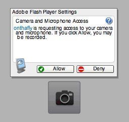
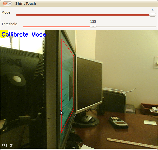
I have yet to give up entirely on ShinyTouch, my experiment into creating a touch screen input system which requires virtually no setup. For people who haven’t read my posts from last year, it works because magically things look shinier when you look at it from an angle. And so if you mount a camera at an angle (It doesn’t need to be as extreme as the screenshot above), you end up seeing a reflection on the surface of the screen (this could be aided by a transparent layer of acrylic or by having a glossy display, but as you can see, mine are matte, but they still work). The other pretty obvious idea of ShinyTouch, is that on a reflective surface, especially observed from a non-direct angle, you can see that the distance from the reflection (I guess my eighth grade science teacher would say the “virtual image”) to the apparent finger, or “real image” is twice the distance from either to the surface of the display. In other words, the reflection gets closer to you when you get closer to the mirror. A webcam usually gives a two-dimensional bitmap of data (and one non-spatial dimension of time). This gives (after a perspective transform) the X and Y positions of the finger. But an important aspect of a touchscreen and what this technology is also capable of, a “zero-touch screen”, is a Z axis: the distance of the finger and the screen. A touchscreen has a binary Z-axis: touch or no touch. Since you can measure the distance between the apparent real finger and it’s reflection, you can get the Z-axis. That’s how ShinyTouch works.

Last year someone was interested and actually contributed some code. Eventually we both agreed that my code was crap so he decided to rewrite it, this time using less PIL and pixel manipulation, and instead, opting for more OpenCV so it’s faster. The project died a bit early this year, and with nothing more to do, I decided to revive it. His code had some neat features:

  • Better perspective performs
  • Faster
  • Less Buggy
  • Simpler configuration (track bars instead of key combinations and editing JSON files)
  • Yellow square to indicate which corner to click when callibrating (actually, I wrote that feature) It was left however, at a pretty unfinished state. It couldn’t do anything more than generate config files through a nice UI and doing a perspective transform on the raw video feed. So in the last few days, I added a few more features.

  • Convert perspective-transformed code into grayscale

  • Apply a 6x6 gaussian blur filter
  • Apply a binary threshold filter
  • Copy it over to PIL and shrink the canvas by 75% for performance reasons
  • Hack a Python flood-fill function to do blob detection (because I couldn’t compile any python bindings for the opencv blob library)
  • Filter those blobs (sort of) Basically, it means ShinyTouch can now do multi-touch. Though the Z-axis processing, which is really what the project is all about still sucks. Like it sucks a lot. But when it does work (on a rare occasion), you get multitouch (yay). If TUIO gets ported (again), it’ll probably be able to interface with all the neat TUIO based apps.

Code here: http://github.com/antimatter15/shinytouch/ Please help, you probably don’t want to try it (yet).

Shinytouch Perspective Transform 23 August 2009

Shinytouch perspective transforms now work!

One big issue with ShinyTouch is that it didn’t transform points correctly, but now it has been totally resolved by stealing this (MIT licensed) from the linux (python!) port of Wiimote Whiteboard (Johnny lee’s famous work). Now it works totally insanely awesomely, no elitists necessary.


TUIO Support 01 August 2009

So even though the algorithms that transform the calibration box aren’t working accurately yet, TUIO support has been made, so you can use apps like TUIO Mouse to control your computer and other touch demo things.


ShinyTouch ideas 13 July 2009

One potential I see for shinytouch is the ability for it to be embedded in a flash application which can be embedded into a web page. Then there could be a web 2.0 style JS API for awesome canvas tag based creations. Or it could just be used to interact with another flash application or game. The reason why this is more likely able to be used as such is because setup for this is so easy that this could actually convince people to do it. With other systems you really have to convince people really well to be dedicated enough to set up the hardware whatever it is. At that point, the software is the easy part and the audience is more than glad to go through the hassle of downloading, running, configuring, and maybe even compiling. But with shinytouch aiming at a different, larger and overall lazier (myself included in this group) audience. This means that it is really important to lower the entry barrier to the lowest possible level. I think being able to just move the webcam a little bit, go to a website and follow simple directions to use their own touchscreen is a very potentially attractive concept. It could even spawn more interest in the touchscreen, natural user interface communities. This is really what I want he project to end up like. It seems quite practical to me. How do you feel about this?

(note that this is my second post entirely from my iPhone)


ShinyTouch Progress Update + Fresnel's Equations 12 July 2009

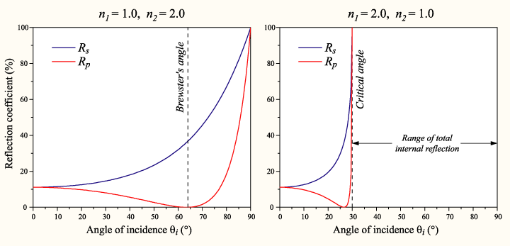
So I was looking through wikipedia to find out if there were some magical equations to govern how it should mix the color of the background screen contents and the reflection and make the application work better. I think Fresnel’s equations fit that description. It basically gives the reflectiveness of the substance from information about the substance, the surrounding substance (air) and the angle of incidence.

Well  this image really is quite intimidating. I wont even pretend to understand it  but it looks like Fresnels equations with different values of n1 and n2 (some ratio for different temperatures). And is the plot on the right the same Total Internal Reflection in FTIR?
A really intimidating image from none other than Wikipedia

It’s quite interesting, partly because the shinyness (and thus the ratios used to combine the background color with the finger to compare) depends on the angle of the webcam to the finger, which depends on the distance (yay for trigonometry?). So the value used isn’t the 50-50 ration that it currently uses in the algorithm universally, but it’s dependent on variables to Fresnel’s Equations and the distance of the finger.

I forgot what this was supposed to describe

Anyway, time for a graphic that doesn’t really explain anything because I lost my train of thought while trying to understand how to use Inkscape!

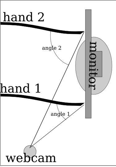
So here’s something more descriptive. The two hands (at least it’s not 3, and why they’re just lines with no fingers isn’t my fault) and they’re positioned at different locations, one (hand 1) is close to the camera while the second (hand 2) is quite far away. Because of magic and trigonometry, the angle of the hand is greater when it’s further away. Also, this plugs into Fresnel’s Equations which mean the surface is shinier for where hand 2 is touching while it’s less shiny for hand 1. So the algorithm has to adjust for the variation (and if this works, then it might not need the complex region specific range values).

Notice how Angle 2 for hand 2 is much larger than angle 1 because of how it
Yay For Trig!

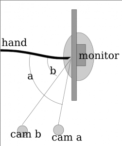
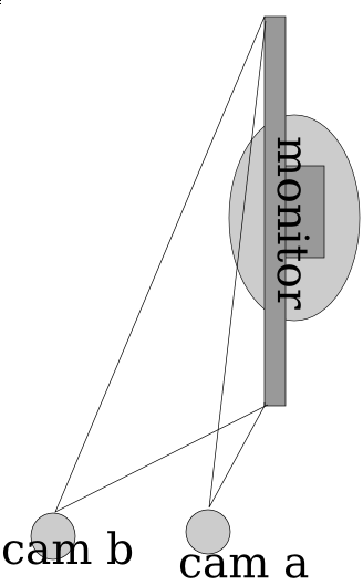
So here it’s pretty ideal to have the angle be pretty extreme right? Those graphs sure seem imply that extreme angles are a good thing. But no, because quite interestingly, the more extreme the angle is, then the less accurate the measures from the x axis become. So in the image below, you can see that cam b is farther from the monitor (and thus has a greater angle from the monitor) and it can discern far more accurately depth than than cam a. The field of view for cam a is squished down to that very thin angle whereas the cam b viewing area is far larger. Imagine if there was a cam c which was mounted directly in front of the monitor, it would suffer from no compression of the x axis like a _or _b but instead it has full possible depth.

the more extreme the angle is  then the lower the resolution of the usable x axis becomes. So while you get better accuracy (shinier = easier to detect) the accuracy point you can reduce it to declines proportionally.
Extreme angles have lower precision

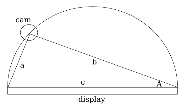
So for the math portion, interestingly, the plot for the decline in % of the total possible width is equivalent to the 1-sin() (I think, but if I’m wrong then it could be cos() and i suck at math anyway).

So since it
More Trig!

So if you graph out 1-sin(n) then you get a curve where it starts at 100% when the angle the camera is positioned at is 0 degrees from an imaginary line perpendicular to the center of the surface, and it approaches 0% as the degree measure reaches 90 deg.

So interestingly when you plot it, basically what happens is a trade-off between the angle the camera is at and the precision (% of ideal maximum horizontal resolution) and accuracy (shinyness of reflection). I had the same theory a few days ago, even before I discovered Fresnel’s Equations, though mine was more linear. I thought that it was just a point in which the values dropped for the shinyness. I thought that the reason the monitor was shinier from the side is that it was beyond the intended viewing angle, so since there is less light at the direction, the innate shinyness is more potent.

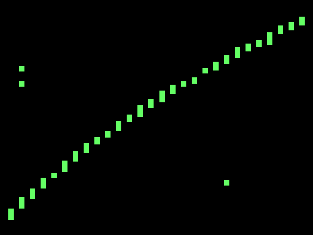
So what does this mean for the project? Well, it confirms my initial thoughts that this is far too complicated for me to do alone, and makes me quite sad (partly because of the post titled Fail that was published in january). It’s really far too complicated for me. Right now the algorithm I use is very approximate (and noticably so). The formula improperly adjusts for perception and so if you try to draw a straight line across the monitor, you end up with a curved section of a sinusoidal-wave.

Trying to draw a straight line across the screen ends up looking curved because it uses a linear approximate distortion adjustment algorithm. Note that the spaces between the bars is because of the limited horizontal resolution  partly due to the angle  mostly due to hacks for how slow python is.
Issues with algorithm

So it’s far more complicated than I could have imagined at first, and I imagined it as far too complicated for me to venture in this alone. But I’m trying even with this sub-ideal situation. So the rest of the algorithm for now will also remain with more linear approximations. I’m going to experiment in making more linear approximations of the plot of Fresnel’s equations. And hopefully it’ll work this time.